Physics A Level | Chapter 25: Motion of charged particles 25.5 Discovering the electron
Today, we know a lot about electrons and we use the idea of electrons to explain all sorts of phenomena, including electric current and chemical bonding. However, at the end of the 19th century, physicists were only just beginning to identify the tiny particles that make up matter.
One of the leaders in this field was the English physicist J.J. Thomson (Figure 25.14). In the photograph, he is shown with the deflection tube that he used in his discovery of the electron.
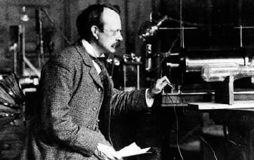
His tube was similar in construction to the deflection tube shown in Figure 25.9. At one end was an electron gun that produced a beam of electrons (which he called ‘cathode rays’). Two metal plates allowed him to apply an electric field to deflect the beam, and he could place magnets outside the tube to apply a magnetic force to the beam. Here is a summary of his observations and what he concluded from them:
- The beam in his tube was deflected towards a positive plate and away from a negative plate, so the particles involved must have negative charge. This was confirmed by the deflection of the beam by a magnetic field.
- When the beam was deflected, it remained as a tight, single beam rather than spreading out into a broad beam. This showed that, if the beam consisted of particles, they must all have the same mass, charge and speed. (Lighter particles would have been deflected more than heavier ones; particles with greater charge would be deflected more, and faster particles would be deflected less.)
- By applying both electric and magnetic fields, Thomson was able to balance the electric and magnetic forces so that the beam in the tube remained straight. He could then calculate the charge-to-mass ratio $\frac{e}{{{m_e}}}$ for the particles he had discovered. Although he did not know the value of either e or me individually, he was able to show that the particles concerned must be much lighter than atoms. They were the particles that we now know as electrons. In fact, for a while, Thomson thought that atoms were made up of thousands of electrons, although his ideas could not explain how so many negatively charged particles could combine to produce a neutral atom.
The magnitude of the charge e of an electron is very small ($1.60 \times {10^{ - 19}}\,C$) and difficult to measure. The American physicist Robert Millikan devised an ingenious way to do it. He observed electrically charged droplets of oil as they moved in electric and gravitational fields and found that they all had a charge that was a small integer multiple of a particular value, which he took to be the magnitude of the charge on a single electron, e. Having established a value for e, he could combine this with Thomson’s value for $\frac{e}{{{m_e}}}$ to calculate the electron mass ${{m_e}}$.
Question
10) The charge-to-mass ratio $\frac{e}{{{m_e}}}$ for the electron is $1.76 \times {10^{11}}\,C\,k{g^{ - 1}}$.
Calculate the mass of the electron using $e = 1.60 \times {10^{ - 19}}\,C$.
EXAM-STYLE QUESTIONS
1) A scientist is doing an experiment on a beam of electrons travelling at right angles to a uniform magnetic field of flux density B. The graph shows the variation of the magnetic force F acting on an electron with the speed v of the electron.
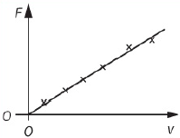
The gradient of the graph is G. The magnitude of the charge on the electron is e.
What is the correct relationship for the magnetic flux density B? [1]
A: $B = G$
B: $B = G \times e$
C: $B = \frac{G}{e}$
D: $B = \frac{e}{G}$
2) The magnetic force BQv causes an electron to travel in a circle in a uniform magnetic field.
Explain why this force does not cause an increase in the speed of the electron. [3]
3) An electron beam is produced from an electron gun in which each electron is accelerated through a potential difference (p.d.) of $1.6 kV$. When these electrons pass at right angles through a magnetic field of flux density $8.0 mT$, the radius of curvature of the electron beam is $0.017 m$.
Calculate the ratio (known as the specific charge of the electron). [4]
4) Two particles, an $\alpha - $particle and a ${\beta ^ - }$-particle, are travelling through a uniform magnetic field. They have the same speed and their velocities are at right angles to the field. Determine the ratio of:
a: the mass of the $\alpha - $particle to the mass of the ${\beta ^ - }$-particle [2]
b: the charge of the $\alpha - $particle to the charge of the ${\beta ^ - }$-particle [2]
c: the force on the $\alpha - $particle to the force on the ${\beta ^ - }$-particle [2]
d: the radius of the $\alpha - $particle’s orbit to the radius of the ${\beta ^ - }$-particle’s orbit. [2]
[Total: 8]
5) A moving charged particle experiences a force in an electric field and also in a magnetic field. State two differences between the forces experienced in the two types of field. [2]
6) This diagram shows the path of an electron as it travels in air. The electron rotates clockwise around a uniform magnetic field into the plane of the paper, but the radius of the orbit decreases in size.
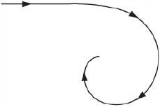
a: i- Explain the origin of the force that causes the electron to spiral in this manner. [2]
ii- Explain why the radius of the circle gradually decreases. [2]
b: At one point in the path, the speed of the electron is $1.0 \times {10^7}\,m\,{s^{ - 1}}$ and
i- the magnetic flux density is $0.25 T$. Calculate:
ii- the force on an electron at this point due to the magnetic field [2]
the radius of the arc of the circular path at this point. [2]
[Total: 8]
7) This diagram shows an arrangement to deflect protons from a source to a detector using a magnetic field. The charge on each proton is $+e$. A uniform magnetic field exists only within the area shown. Protons move from the source to the detector in the plane of the paper.
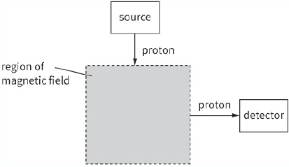
a: i- Copy the diagram and sketch the path of a proton from the source to the detector. Draw an arrow at two points on the path to show the direction of the force on the proton produced by the magnetic field. [3]
ii- State the direction of the magnetic field within the area shown. [1]
b: The speed of a proton as it enters the magnetic field is $4.0 \times {10^6}\,m\,{s^{ - 1}}$.
The magnetic flux density is $0.25 T$. Calculate:
i- the magnitude of the force on the proton caused by the magnetic field [1]
ii- the radius of curvature of the path of the proton in the magnetic field. [2]
c: Two changes to the magnetic field in the area shown are made. These changes allow an electron with the same speed as the proton to be deflected along the same path as the proton. State the two changes made. [2]
[Total: 9]
8) This diagram shows a thin slice of semiconductor material carrying a current in a magnetic field at right angles to the current.
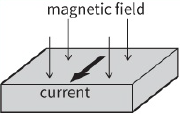
a: The current in the slice is due to the movement of free electrons.
i- Add + and − signs to the diagram to show the charge separation caused by the Hall effect. Explain why the charges separate. [3]
ii- Explain how an electron can eventually move in a straight line along the slice. [1]
b: The Hall voltage is measured using the same slice of semiconductor, the same current and the same magnetic field, but with the laboratory at two temperatures, one significantly higher than the other.
Describe and explain the changes in the magnitude of the number density, the drift velocity of the charge carriers and the Hall voltage in the two experiments. [5]
[Total: 9]
9) This diagram shows an electron tube. Electrons emitted from the cathode accelerate towards the anode and then pass into a uniform electric field created by two oppositely charged horizontal metal plates.
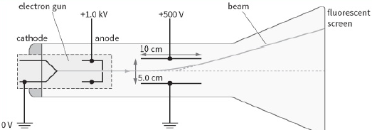
a: i- Explain why the beam curves upwards between the plates. [2]
ii- Explain how the pattern formed on the fluorescent screen shows that all the electrons have the same speed as they leave the anode. [2]
b: Write down an equation relating the speed of the electrons v to the potential difference ${V_{ac}}$ between the anode and the cathode. [1]
c: The deflection of the beam upwards can be cancelled by applying a suitable uniform magnetic field in the space between the parallel plates.
i- State the direction of the magnetic field for this to happen. [1]
ii- Write down an equation relating the speed of the electrons v, the electric field strength E that exists between the plates and the magnetic flux density B needed to make the electrons pass undeflected between the plates. [2]
iii- Determine the value of B required, using the apparatus shown in the diagram, given that for an electron the ratio $\frac{e}{{{m_e}}} = 1.76 \times {10^{11}}\,C\,K{g^{ - 1}}$. [4]
[Total: 12]
10) Protons and helium nuclei from the Sun pass into the Earth’s atmosphere above the poles, where the magnetic flux density is $6.0 \times {10^{ - 5}}\,T$. The particles are moving at a speed of $1.0 \times {10^6}\,m\,{s^{ - 1}}$ at right angles to the magnetic field in this region. The magnetic field can be assumed to be uniform.
a: Calculate the radius of the path of a proton as it passes above the Earth’s
pole. [3]
$mass\,of\,a\,helium\,nucleus = 6.8 \times {10^{ - 27}}\,kg$
$charge\,on\,a\,helium\,nucleus = 3.2 \times {10^{ - 19}}\,C$
b: Sketch a diagram to show the deflection caused by the magnetic field to the paths of a proton and of a helium nucleus that both have the same initial velocity as they enter the magnetic field. [2]
[Total: 5]
11) This diagram shows a thin slice of metal of thickness t and width d. The metal slice is in a magnetic field of flux density B and carries a current I, as shown.
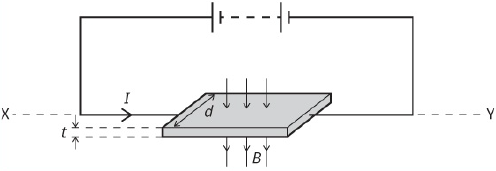
a) Copy the diagram and mark:
i- the side of the slice that becomes negative because of the Hall effect [1]
ii- where a voltmeter needs to be placed to measure the Hall voltage. [1]
b: Derive an expression for the Hall voltage in terms of I, B, t, the number density of the charge carriers n in the metal and the charge e on an electron. [3]
c: Given that $I = 40 mA$, $d = 9.0 mm$, $t = 0.030 mm$, $B = 0.60 T$, $e = 1.6 \times {10^{ - 19}}\,C$
and $n = 8.5 \times {10^{28}}\,{m^{ - 3}}$, calculate:
i- the mean drift velocity v of the free electrons in the metal [2]
ii- the Hall voltage across the metal slice [2]
iii- the percentage uncertainty in the mean drift velocity v of the electrons, assuming the percentage uncertainties in the quantities are as shown.
[1]
| Quantity | $\% $ uncertainty |
| Current I | 1.3 |
| Width d | 2.5 |
| Thickness t | 3.0 |
| Number density of charge carriers n | 0.2 |
d: i- Explain why, in terms of the movement of electrons, the Hall voltage increases when I increases. [2]
ii- A Hall probe used to determine the magnetic flux density of a magnetic field uses a thin slice of a semiconductor rather than metal. Explain
why a semiconductor is used. [2]
e: Explain why, when the slice of metal is rotated about the horizontal axis XY, the Hall voltage varies between a maximum positive value and a maximum negative value. [2]
[Total: 16]
SELF-EVALUATION CHECKLIST
After studying the chapter, complete a table like this:
| I can | See topic… | Needs more work | Almost there | Ready to move on |
| use Fleming’s left-hand rule to determine the direction of the force on a charge moving in a magnetic field | 25.1 | |||
|
recall and use: $F = BQv\,sin\theta $ |
25.1 | |||
| describe the motion of a charged particle moving in a uniform magnetic field perpendicular to the direction of motion of the particle | 25.2 | |||
| explain how electric and magnetic fields can be used in velocity selection of charged particles | 25.3 | |||
| understand the Hall effect and the origin of the Hall voltage | 25.4 | |||
|
derive and use the expression for Hall voltage: ${V_H} = \frac{{BI}}{{ntq}}$ |
25.4 | |||
| use a Hall probe to measure magnetic flux density. | 25.4 |